 English
 简体中文

Short answer: The only correct entry point for slewing-bearing selection is the overturning moment: convert upper-structure weight, load center and a dynamic factor into a peak moment, then read it against the manufacturer's combined load-capacity curves - never scale from machine tonnage. Mounting matters just as much: face flatness within 0.5 mm per meter, 10.9-class bolts tightened crosswise. An out-of-flat mount ovalizes the raceway and early pitting follows no matter how large the bearing is.
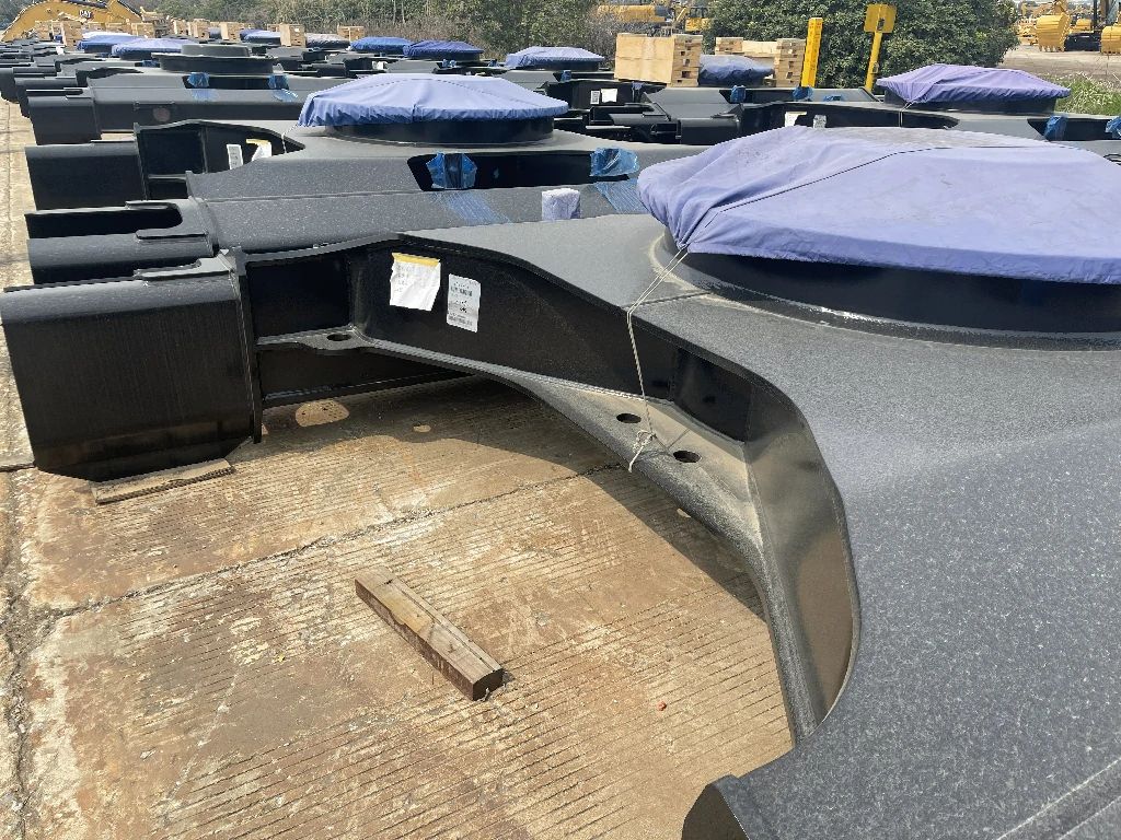
1. From machine data to overturning moment
Three load groups act on the bearing: axial (weight of structure plus payload), radial (in-plane horizontal, from grades and swing inertia), and the overturning moment (load eccentricity times the moment arm). Dynamic factors are not optional: lifting class starts at 1.25, crushing class at 1.5, drilling thrust duty at 1.6. The classic failure story - statics say it fits, pitting appears early - is almost always a missed dynamic factor.
Read the working point against the capacity curves (moment on one axis, axial load on the other, a family of life curves). The point must sit below-left of the target-life curve with 10-15 percent margin. Run the check twice: static capacity against structural yielding, dynamic capacity against raceway fatigue based on swing count.
2. The mounting face: the underestimated failure source
A slewing bearing is a thin-walled large-diameter ring whose stiffness depends almost entirely on the carrier. Face flatness must stay within 0.5 mm per meter with no more than 1.5 mm cumulative across the face; an out-of-flat mount, pulled tight by bolts, deforms the raceway oval and multiplies local contact stress. The textbook failure - clearance reads fine on delivery, pitting within a few hundred hours - lives here. Verify with a straightedge and feelers across the full face; never rely on the machine shop's promise.
Bolts: 10.9 class minimum, crosswise two-pass tightening, torque within plus or minus 5 percent. Poor hole positions leave some bolts unloaded and the raceway clamp uneven. On acceptance, pull 8-12 bolts with a hydraulic tensioner to verify actual preload - more revealing than torque alone.
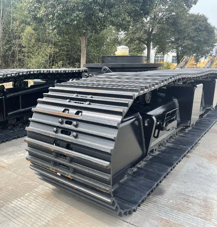
3. Clearance, hose routing and gear checks
Delivery clearance follows load type: tighter for axial-dominated duty, slightly larger where overturning dominates. Accept with an indicator measuring rotational play against the contract value. Hoses and harnesses must route through the central slip ring, never wrapped around the outer ring - the commonest hidden error in the field, since a dragging hose applies a permanent radial force to the bearing.
Gear side: set pinion-to-ring backlash at 0.3-0.5 mm and hold slewing-reducer concentricity within 0.15 mm, or the drive runs noisy and wears one flank. Record delivery clearance and backlash as the baseline for future servicing.
4. Service points
Lubricate the raceway by swing count, not hours: every 5000 swings or 100 hours, whichever first, greasing until fresh grease extrudes at the relief port. Gear teeth take open-gear grease separately. Measure clearance every six months - a clear upward trend means raceway wear is accelerating, and a planned replacement costs an order of magnitude less than a failure.
5. Selection and mounting acceptance checklist
| Item | Requirement | Verification |
|---|---|---|
| Capacity check | 3-direction conversion + dynamic factor 1.25-1.6 | Point on curve with 10-15% margin |
| Mounting flatness | 0.5 mm/m max, 1.5 mm cumulative | Straightedge + feelers, full face |
| Bolts | 10.9 class, crosswise two-pass | Torque within 5% + tensioner sampling |
| Gear backlash | 0.3-0.5 mm | Indicator reading recorded |
Key takeaways
- Select on the overturning-moment capacity curve, never by tonnage scaling; dynamic factors of 1.25-1.6 are not optional.
- Verify both static (yielding) and dynamic (raceway fatigue by swing count) capacity.
- Flatness within 0.5 mm/m is a hard gate - an out-of-flat mount ovalizes the raceway and pitting follows despite a healthy clearance reading.
- Grease by swings (5000 or 100 hours, whichever first) and trend the clearance every six months.
Further reading
360-Degree Slewing Steel Track Undercarriage · MG2500B 25-Ton Steel Track Undercarriage · Selection guide column
Prepared by the MAGEON engineering team from custom project records and factory load-test data. Figures are engineering references; final selection should follow approved drawings and the actual duty spectrum.