 English
 简体中文

Short answer: Early frame cracking on a crawler undercarriage almost never comes from insufficient plate strength. It starts at weld details - toe geometry, lack of fusion and residual stress - which become fatigue initiation points under cyclic loading. Frame welds should be checked against a fatigue load spectrum, not a static strength calculation alone. For critical welds specify 100% visual testing plus 100% magnetic particle inspection, ultrasonic testing on thick full-penetration joints, and ISO 5817 level C or better.
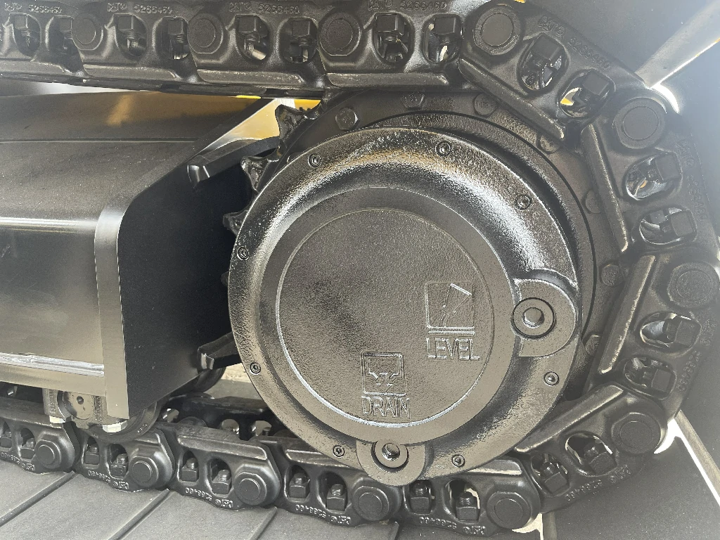
1. Why cracks start at the weld, not in the plate
Base metal yield strength and fatigue limit are documented on the mill certificate. A weld is formed in the shop: toe transition angle, reinforcement height, undercut and root lack of fusion together set the local stress concentration factor. On the same Q355 plate, a smoothly blended toe and a visibly undercut toe can differ by a factor of two to three in fatigue life.
Loading makes it worse. A track frame does not carry a steady static load. Each shoe contact produces a low-frequency load cycle, and every revolution loads and unloads the roller seats and tensioner mounts. At eight hours a day and 2 km/h travel speed, a machine can accumulate several hundred thousand cycles a year, which is high-cycle fatigue territory.
2. Three weld locations that deserve the most control
First, the track roller seat to frame web weld, which takes roller reaction and impact directly. Second, the tensioner cylinder mount, where force direction changes with tension and often carries eccentricity. Third, the slew bearing flange circumferential weld, which carries the full overturning moment. All three share discontinuous load paths, dense weld clusters and very difficult field repair.
Design should keep butt welds away from peak stress regions, move them into lower-stress zones, use full-penetration grooves and grind the toe blend after welding. On the process side, fix the WPS and PQR, and record consumable batch and preheat temperature against the material heat number so any later crack can be traced to a specific operation.
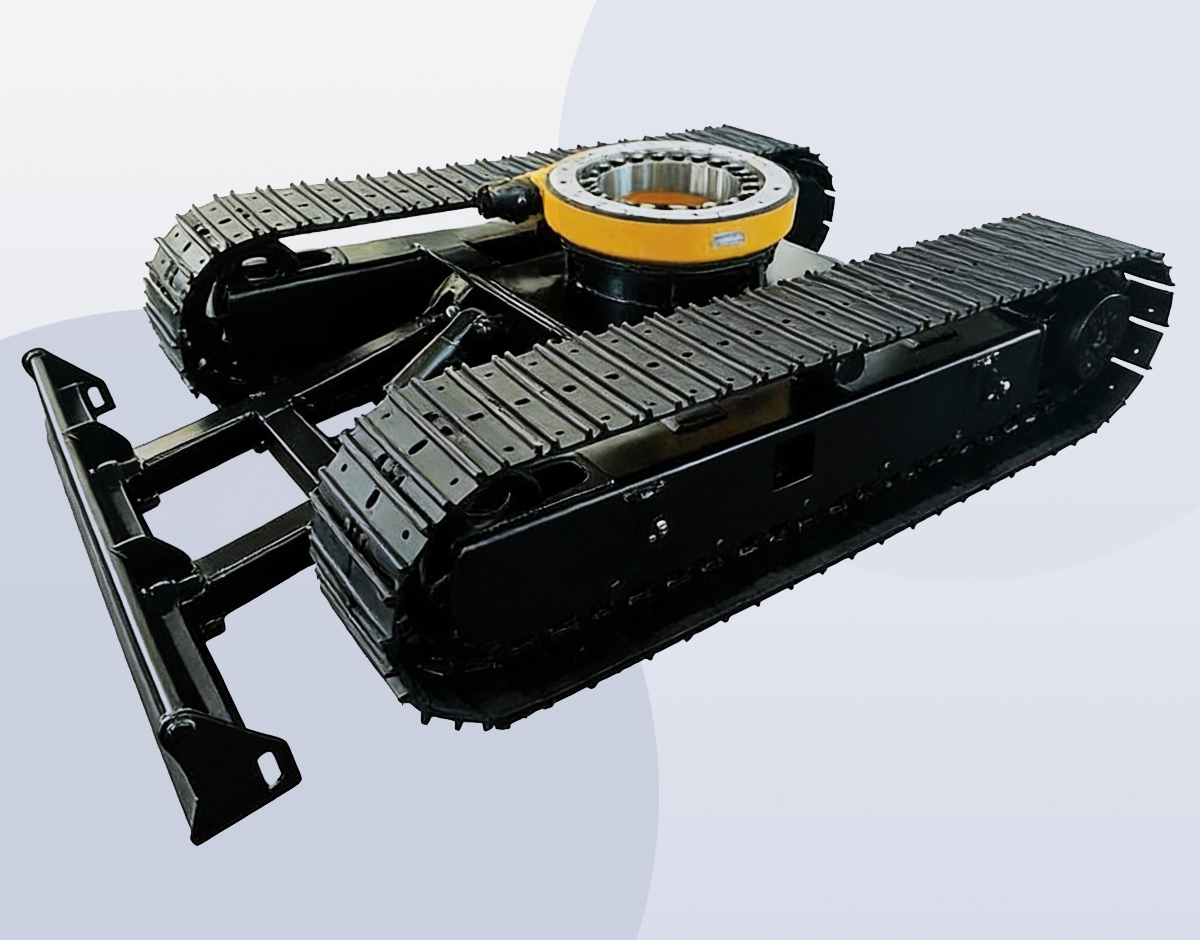
3. Building a fatigue load spectrum that is actually useful
Checking only full static weight times a safety factor underestimates eccentric loading and impact. A workable engineering convention is a 1.2-1.3 dynamic factor for general earthmoving, 1.5 for abrasive aggregate and mining duty, plus a separate check with one track carrying 70% of total load for rutted ground or ditch crossing.
The spectrum should include at least four cases: loaded stationary, loaded gradient climbing, single-track eccentric travel, and abrupt stop or counter-rotation. Drilling rigs and cranes add overturning moment and outrigger reaction. Weighting these cases by frequency of occurrence is far more useful than quoting a single nominal tonnage.
4. Inspection mix, timing and documentation
Use three layers: visual testing on 100% of welds for reinforcement, undercut and spatter; magnetic particle inspection on 100% of the three critical weld groups for surface and near-surface cracks; and ultrasonic testing on at least 20% of full-penetration joints thicker than 20 mm. Follow with a 1.25x rated static load hold and strain recheck before release.
Deliverables should include material heat traceability, WPS/PQR copies, NDT reports and the load test report. These four are the standard checklist in an OEM supplier audit, and they are what allow a later crack to be attributed to design, workmanship or duty rather than to guesswork.
5. Weld Location vs Inspection Requirement
| Weld location | Dominant load | Recommended NDT | Acceptance |
|---|---|---|---|
| Roller seat to web | Roller reaction + impact | VT 100% + MT 100% | ISO 5817 level C |
| Tensioner mount | Eccentric cyclic tension | VT 100% + MT 100% | ISO 5817 level C |
| Slew bearing flange | Overturning moment | VT + MT + 20% UT | ISO 5817 level B/C |
| Frame web butt weld | Bending and torsion | VT 100% + UT sample | ISO 5817 level C |
Key takeaways
- Weld detail, not plate strength, governs frame fatigue life; static strength approval is not durability approval.
- Roller seats, tensioner mounts and slew bearing flanges need 100% magnetic particle inspection.
- Use 1.2-1.5 dynamic factors plus a 70% single-track eccentric case in the fatigue spectrum.
- Material traceability, WPS/PQR, NDT and load test reports are the core OEM audit package.
Further reading
Steel Crawler Undercarriage · Selection Guide · Technical Support · Products
Prepared by the MAGEON engineering team from custom project records and factory load-test data. Figures are engineering references; final selection should follow approved drawings and the actual duty spectrum.