 English
 简体中文

The performance of a crawler undercarriage comes from how five systems work together - frame stiffness, roller set fit, track chain engagement, tensioning precision and hydraulic matching - rather than from any single component in isolation. This article takes the undercarriage apart and shows where each part sits in the load path, and what its failure looks like in service. That framework is the basis for judging whether an undercarriage is genuinely reliable.
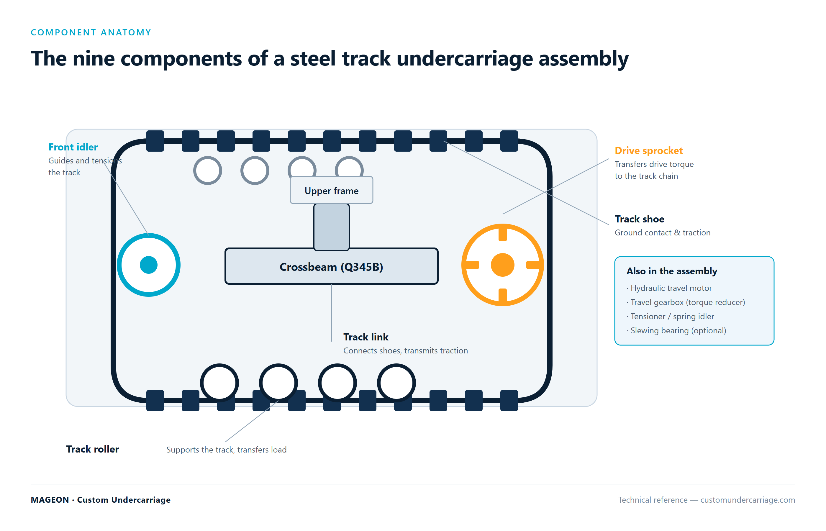
1. The Frame and Travel Gear: Where Every Load Starts
The frame carries all vertical load, tractive force and overturning moment, and is the starting point of the load path. Its meaningful measure is not weight but the ratio of stiffness to fatigue life: two frames of equal weight can differ by more than 30% in load capacity purely through steel grade selection and weld layout.
Three extreme conditions govern frame design: maximum static load at standstill, maximum torque on a gradient, and maximum overturning moment with one track assembly lifted. The third is most often overlooked, yet it determines the frame's torsional rigidity on rough ground. Insufficient torsional rigidity shows up as fatigue cracking at welds after long service.
| Frame construction | Tonnage range | Advantage | Limit |
|---|---|---|---|
| H-beam welded frame | 1T - 30T | Light, economical, easy to modify | Limited torsional rigidity |
| Box-section closed frame | 10T - 80T | High torsional and bending stiffness | Higher weight and cost |
| Forged or cast structure | Above 80T | Best stiffness and consistency | High tooling cost, uneconomic in small batches |
2. Track Rollers and Sprockets: The Two Ends of Ground Contact
Track rollers provide most of the contact area and carry the distributed static load, with dynamic load superimposed on a fully loaded climb. Uneven roller wear almost always traces back to two causes: a frame that has deformed so the wheels no longer sit coplanar, or a single failed roller bearing that redistributes load onto its neighbours.
The sprocket sits at the active end of the chain and reacts the full tractive force. Tooth face pitting is the most common steel-undercarriage sprocket failure mode, and three variables govern it: tooth surface hardness, lubrication condition, and the match between chain pitch and sprocket tooth profile. The third is routinely overlooked - once the chain stretches, contact shifts from full surface to point loading, and pitting rate multiplies.
3. Track Chain and Shoes: The Fatigue Component Nobody Budgets For
The track chain of pins, bushings and links is the only component in the undercarriage subject to alternating load. Pin shear and bushing crushing form the fatigue failure path of a link, with typical life in the 2,000-4,000 hour range. The track shoe carries the link and its thickness and grouser height set the limits of wear and shear resistance.
When grouser height wears down far enough, the chain loses engagement depth on the sprocket and begins climbing or skipping teeth. This is the real explanation behind a great many unexplained chain breakages - not tension, but grouser height already past the critical limit.
4. Tensioning and Travel Gear: The Precision Step That Gets Missed
The tensioner absorbs the length change caused by chain pitch elongation and holds working tension in the chain. Industrial-grade products mark a datum on the tensioner rod, which gives a quick read on how fast the chain is stretching. That single detail is worth more in daily service than many of the parameters in the manual.
A common misconception deserves correcting: many operators believe tighter is always better. Over-tensioning stretches chain pitch, accelerates pin and bushing wear, and consumes roller travel so bearings fail early. Under-tensioning lets the chain climb the sprocket, accelerates wear and risks breakage. The correct approach is deflection-based, holding slack span droop within the specified range.
5. Hydraulic Drive Matching: The Final Link to Power
The combination of hydraulic motor and gearbox sets the undercarriage's travel speed and torque ceiling, but the real matching problem lies in whether the machine's duty cycle and the chassis output actually agree. An excavator needs low-speed high-torque with fine flow control; a drilling rig needs stable output and shock absorption under breakout load; a crane needs travel function that stays controlled during slew.
Matching motor displacement and reduction ratio to the machine's work cycle is far more effective than simply chasing higher torque. Excess torque reserve is useless in the low-speed range while adding weight, slowing travel and degrading control precision.
6. How to Assess Undercarriage Reliability
When evaluating a supplier's undercarriage, work through the sequence: examine frame welds and material traceability first, then roller bearing specification and sealing, then verify chain pitch against sprocket tooth profile, and only then look at motor and gearbox figures. Reversing that order puts your attention on the most easily replaced components while missing the actual weak point.
For component-level specifications and configuration options, see the Steel Crawler Undercarriage and Rubber Crawler Undercarriage sections; tonnage-specific parameters are listed under Products, and component-level service detail is covered in Maintenance Knowledge. For selection methodology, start with Selection Guide, or compare configurations for comparable machines in Applications.