 English
 简体中文

The stability advantage of a steel track undercarriage on a crawler crane comes from the fact that the machine's stability is a function of the track gauge and the ground pressure, and both are directly engineered. A crane is a machine whose whole purpose is to hold a load at a radius, and the moment created by that load has to be resisted by the undercarriage pressing into the ground. Steel track undercarriages give two distinct advantages over wheeled or rubber-track alternatives: a wide, rigid frame that spreads the overturning moment across the full track length, and a high ground bearing pressure that means the track sinks slightly into the ground rather than sliding — effectively increasing the machine's effective stability radius. MAGEON supplies customised steel track undercarriages from 1 to 60 tons with 200–500 mm track width and an optional integrated 360° slewing bearing rotary system, and both features are directly relevant to crane work.
This article covers how stability actually works on a crawler crane, which parameters drive it, and what to specify to get a stable chassis for lifting operations.
How is crawler crane stability actually determined?
Stability on a crawler crane is governed by the tipping moment. The rated capacity of any crane is the load that, at a given radius, would bring the overturning moment to the tipping condition — and the tipping condition is reached when the resultant of the machine's weight and the load falls outside the support polygon defined by the tracks.
Two things therefore make a crawler crane stable. The first is a large support polygon, which means a long track contact length and a wide track gauge, both of which are engineering parameters of the undercarriage rather than of the upper structure. The second is a high margin against sliding, which comes from ground bearing pressure: a track that presses into the ground resists the horizontal component of the hoist load, and a track that merely rests on the ground does not.
This is where the steel track undercarriage differs fundamentally from a wheeled or rubber-track alternative. A steel grouser bar penetrating the ground provides mechanical resistance to sliding; a rubber pad grips by friction over a compliant area, which means less resistance to a horizontal pull at the moment it is most needed. On a crane picking at radius on soft ground, this difference is the difference between a controlled lift and a slide.
How does the track frame contribute to stability?
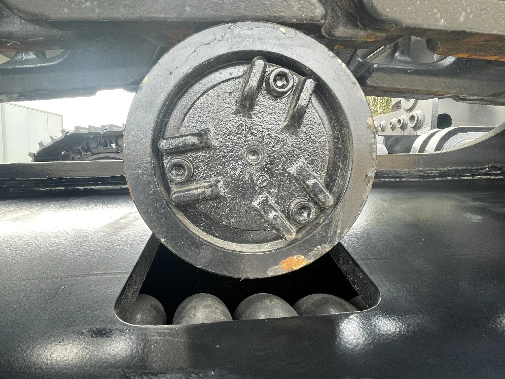
Through torsional rigidity. When a crane slews with a load at radius, the upper structure applies a twisting moment to the undercarriage. MAGEON's chassis beam is Q345B high-strength steel, with the welded structure optimised for load capacity and torsional rigidity. A frame that flexes in torsion effectively lengthens the machine's tipping axis, because the upper structure is no longer sitting squarely over the track line — it is leaning.
The frame also determines the track length available for load transfer. A longer track spreads the machine's weight over a longer footprint, which means the ground pressure under the tracks drops for a given machine weight, which means the tracks do not press into the ground as firmly. There is a genuine trade-off here: long tracks improve the support polygon but reduce ground bearing pressure, while short tracks do the reverse. The correct balance is set against the ground condition — soft ground favours more length, hard ground and heavy lifts favour the bearing pressure that resists sliding.
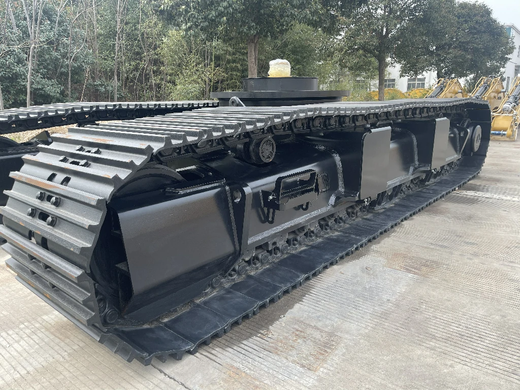
The complete assembly also matters: steel tracks, track links, track rollers, front idlers, drive sprockets, hydraulic motors, travel gearboxes and crossbeams are supplied as one unit, with the load path designed as a system rather than assembled from separate suppliers' components. For a crane, where the load case is well defined and the consequences of a frame failure are severe, that system-level design is the point.
What does the 360° slewing bearing contribute on a crane?
Substantially, and it is a specific advantage rather than a general one. A crawler crane with a fixed chassis must move the whole machine to change its working direction. A crane with an integrated 360° slewing bearing rotary system can rotate the upper structure relative to the undercarriage while the tracks stay put — which means the machine can work in a confined site, a congested yard, or a column-supported building interior where repositioning the tracks is impossible.
On cranes specifically, this is what makes a compact crawler crane practical for indoor or tight-access work, and it eliminates the repeated track-moving cycle from the working cycle. MAGEON builds the slewing-bearing version across the same 1–60 ton envelope as the standard steel track undercarriage, so the rotary capability does not force a smaller machine class. The slewing torque requirement is a design input and should be stated at enquiry stage, since it is what determines the bearing specification.
Which applications need the strongest stability?
Three classes stand out. The first is pick-and-carry work on rough ground — construction site crane work where the crane sets up on uncompacted fill and must place loads accurately, and where a machine that shifts a few centimetres under load is a safety problem rather than an inconvenience.
The second is heavy lift at radius on soft ground. Here the tipping moment is largest and the ground is least able to resist it, and the grouser bar's mechanical penetration into the soil is doing structural work. A rubber track in the same application has to rely on friction, and the loss of grip is progressive rather than sudden, which makes it harder to detect.
The third is confined-site work where a 360° slewing bearing lets the machine operate without repositioning — the case MAGEON's slewing-bearing product was designed for, serving drilling rigs, crushers, excavators, piling machines and lifting equipment in confined working conditions.
| Stability factor | Contribution on a crawler crane | Engineered through |
|---|---|---|
| Track gauge | Widens the support polygon, resists tipping | Track width, 200–500 mm selectable |
| Track contact length | Lengthens the support polygon | Overall undercarriage dimensions |
| Ground bearing pressure | Resists horizontal slide under hoist load | Machine weight, track width, grouser profile |
| Torsional rigidity | Keeps the upper structure square over the track line | Q345B welded frame and crossbeam section |
| Slewing capability | 360° working direction without repositioning | Optional integrated slewing bearing |
What are the limitations to be aware of?
The first is ground condition. A steel track's stability advantage depends on the ground resisting penetration — on a hard, sealed surface such as concrete or asphalt, the grouser bar cannot penetrate and the machine's resistance to sliding drops to a friction-limited value. This is a common site condition and it is worth telling the supplier, because it changes both the track specification and the outrigger or matting arrangement that may be needed.
The second is the trade-off already mentioned: increasing track length to widen the support polygon reduces ground bearing pressure, and on soft ground a machine can settle rather than slide. That is normally the safer failure mode, but it means the crane's setup conditions have to be assessed.
The third is ground damage. A steel track on a customer's yard or an operating plant leaves marks and can damage paving. For crane work on a finished site, a steel track with bolt-on rubber pads is often the right compromise — MAGEON's 3–15 ton rubber-padded steel track undercarriage, at 2–4 km/h travelling speed, retains the steel load path while reducing surface marking. Note that this is a 3–15 ton class product, so a larger crane may need the bare steel configuration or a separately engineered variant.
How do you specify a crawler crane undercarriage?
Beyond the standard five — machine weight and load distribution, mounting interface dimensions including bolt pattern and drive shaft height, required travelling speed, ground and duty conditions, and drive configuration — a crane enquiry should state the maximum lift radius and the lift weight at that radius, the slew torque requirement if a slewing bearing is wanted, and the ground bearing conditions the machine will set up on. Those three inputs drive the stability design directly.
Drawings in DXF, DWG or PDF are accepted and are the fastest route to an accurate quotation. MAGEON surveys them one-to-one against the host structure, confirming mounting flange dimensions, bolt pattern, drive shaft height and hydraulic interface before manufacturing, so the chassis bolts on directly.
Commercially, the minimum order quantity is one set, standard lead time is approximately 20 days for one set and 30 days for two to three sets, with longer timelines negotiated for volume orders. Every chassis ships with a one-year or 1,000-hour warranty and ISO 9001:2015 certification, with video outgoing inspection provided before dispatch. Packaging is a wooden pallet or wooden case, FOB at Shanghai, Ningbo or Shenzhen, with delivery by sea, air or land.
Frequently asked questions
Why is a steel track more stable than a rubber track on a crane?
Because of how each resists a horizontal force. A steel grouser bar penetrates the ground, so resistance to sliding comes from mechanical bearing of the soil rather than from friction at a compliant contact patch. A rubber pad resists through friction over a wide area, and that friction coefficient falls under high load, which is precisely when a crane needs it most. On a soft site where the tipping moment is large, this difference decides whether the machine holds position or creeps.
Does track length or track width help stability more?
They do different things. Track width widens the support polygon laterally and lowers ground pressure; track length lengthens the support polygon fore-and-aft. Width is usually the more effective choice for crane stability because overturning moment is reacted over the width, and it is also the parameter MAGEON's 200–500 mm range is set up to be tuned against. Lengthening the tracks is constrained by the machine envelope, so it is usually the parameter that is adjusted last, and it does reduce ground bearing pressure if taken too far.
What is a 360° slewing bearing on a crane undercarriage?
An integrated slewing bearing rotary system that lets the upper structure rotate 360° relative to the chassis, so the crane can change working direction without moving the tracks. MAGEON builds this across the same 1–60 ton envelope as the standard steel track undercarriage. On cranes it is what makes confined-site and indoor lifting practical, since the tracks cannot be repositioned in such environments. The slewing torque requirement should be stated at enquiry stage as it determines the bearing specification.
Will a steel track crane undercarriage damage the site surface?
Yes, on paving and finished surfaces, and on soft ground it leaves ruts. This is the usual trade-off against the stability benefit. Where the machine must work on a finished yard or a customer's site, specify a steel track with bolt-on rubber pads — MAGEON's rubber-padded steel track undercarriage covers the 3–15 ton class at 2–4 km/h. For larger cranes where that class does not apply, the option is to discuss the requirement directly during the requirement assessment, since the pad arrangement is an engineering decision against the load case.
How much does the undercarriage affect the crane's rated capacity?
It affects it directly, because the rated capacity is limited by the tipping condition and the tipping condition is determined by the support polygon and the ground bearing pressure. A wider track and a longer track contact length both raise the tipping threshold, and a frame with high torsional rigidity preserves the assumption that the upper structure sits squarely over the track line. A machine fitted with an under-specified chassis will have a lower usable capacity than the upper structure's theoretical rating, which is why the chassis specification belongs in the crane's capacity calculation rather than being treated as a commodity purchase.
What information do you need for a crane chassis quotation?
Total machine weight and load distribution, mounting interface dimensions including bolt pattern and drive shaft height, required travelling speed, ground and duty conditions, and drive configuration — plus maximum lift radius and the lift weight at that radius, the slewing torque requirement if a 360° slewing bearing is required, and the ground bearing conditions at the setup site. Drawings in DXF, DWG or PDF are accepted and MAGEON surveys them one-to-one against the host structure before manufacturing.